







Perform with FCCSA
Join our Content Team to create and share knowledge.
Learn how to be part of it



Be acquainted with our purpose, values, history and all that makes the FCC S.A. essence

A portfolio of products and solutions plenty of innovation, technology and sustainability.

To deliver products with leading edge technology and global quality is just our starting point. That is why we have a series of exclusive services for our customers and that make all the difference on a daily basis.

See in practical terms how innovation is present in the FCC S.A. DNA

Sustainability is present in every solution, delivery and process of our company: learn more.

We are made of synergy! Learn how you can become a FCC S.A. supplier

Learn how it is to work with FCC.S.A. Learn our culture, programs and check for opportunities.

Integrity and transparency are part of what we are. Check our annual reports and see the result of our work.

Find a variety of contents that permeate our businesses and see how you can be a part of what we create around here.

Together, we create more! Be a FCC S.A. partner and generate value for a world in transformation: learn how.

In a world covered by roads, where terrestrial transportation drives the economy by carrying commodities to the ports and bringing back imported products, one fuel reigns supreme: diesel. But it is not only on roads; it is in electric generators, agricultural machinery, mining, and public transportation. In everyone's daily life, diesel is present.
While the gasoline market faces competition from electric vehicles and ethanol, it is estimated that the global diesel market will grow by more than 4% (1) over the next 10 years and that Latin America will be the region in the world where this market will increase most intensely (2). With this expectation and current prices, the pressure to maximize diesel yield from refineries in the region is increasing, as for many of them this is the most profitable product.
The FCC unit, created to maximize high-octane naphtha from heavy streams, also faces pressure to contribute to increasing the refinery's diesel production by boosting the yield of LCO, a product that can be blended into diesel after treatment. The adjustments to maximize this product at the unit are focused on three fronts:
In this article, we will briefly discuss each of these initiatives and their possible impacts on the unit.
For maximizing diesel in a UFCC, the main adjustments in the converter will aim to reduce the severity of catalytic cracking, seeking to minimize the conversion of LCO to naphtha. This reduction in severity involves lowering the reaction temperature and reducing the catalyst/oil ratio, which decreases the availability of catalytic sites and energy for the cracking reactions. For this, the main possible adjustments are:
Unfortunately, when the severity of catalytic cracking is reduced, the overall conversion decreases, not selectively increasing the LCO, which can affect the profitability of the unit, as in the following example, which shows the results of an industrial test to maximize LCO yield by reducing the reaction temperature. In this case, the increase in volumetric yield of slurry exceeded the increase in LCO, and for that the refinery reversed the changes.
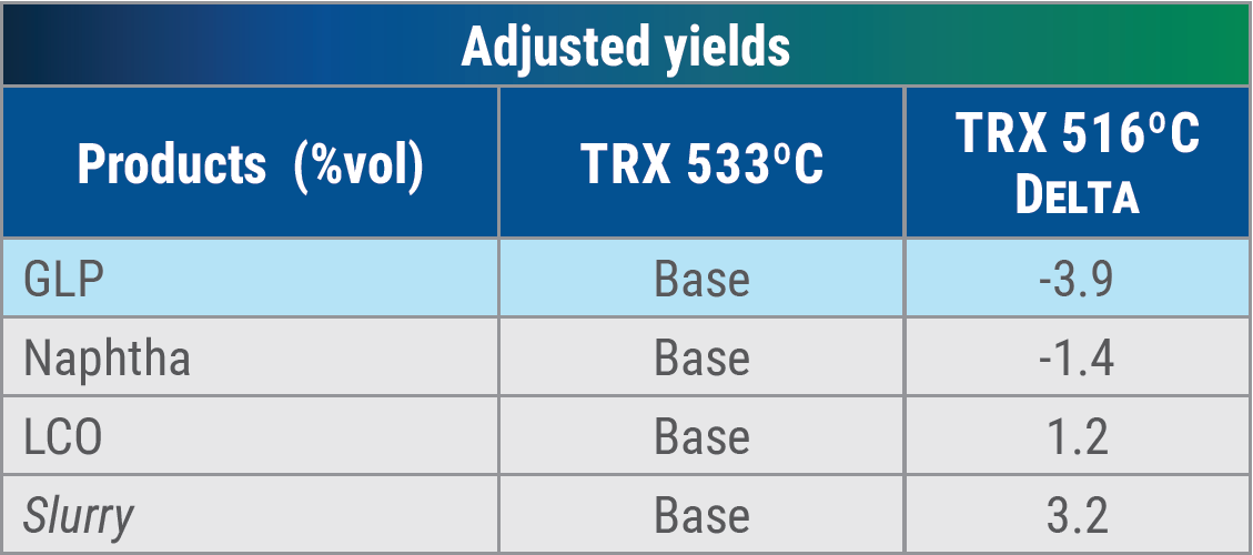
Table 1 - Variation of volumetric yields by TRX reduction – Source: FCCSA database
Each unit will respond differently to the reduction in severity, according to its particularities. Simulation results, combined with financial assessments, can help determine a possible optimal condition.
In addition to the need for economic evaluation, it is important to take into account the limitations of the converter. Reductions in reaction temperature and catalyst circulation can cause coke formation at various points in the unit, as exemplified below:
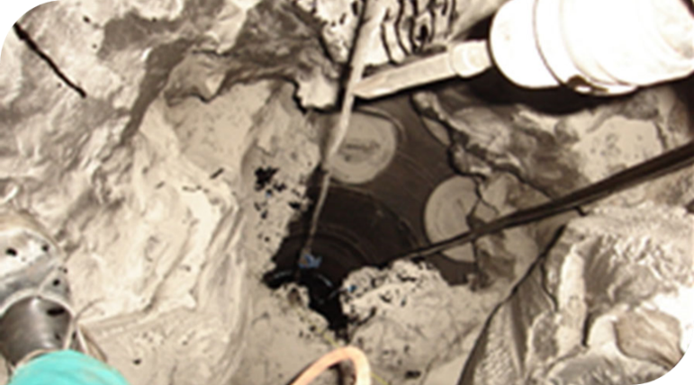
Figure 1 - Coke deposits at the base of the riser - Source: FCCSA’s archives
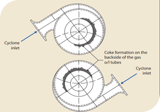
Figure 2 - typical location of coke deposition - Source: FCCSA’s archives
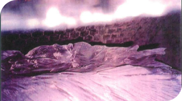
Figure 3 - Coke formed inside cyclones - Source: FCCSA’s archives.
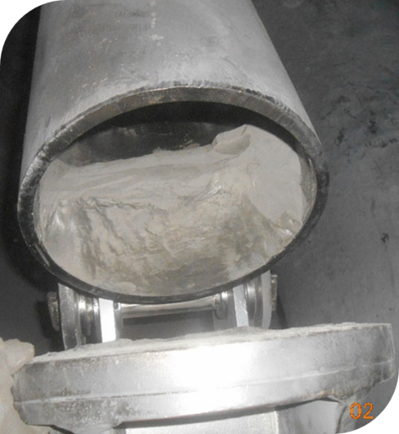
Figure 4 - Formation of coke inside the cyclone’s dip leg - Source: FCCSA’s archives.
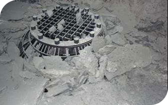
Figure 5 - Coke that detached from the reactor walls causing partial obstruction of the catalyst outlet - Source: FCCSA’s archives
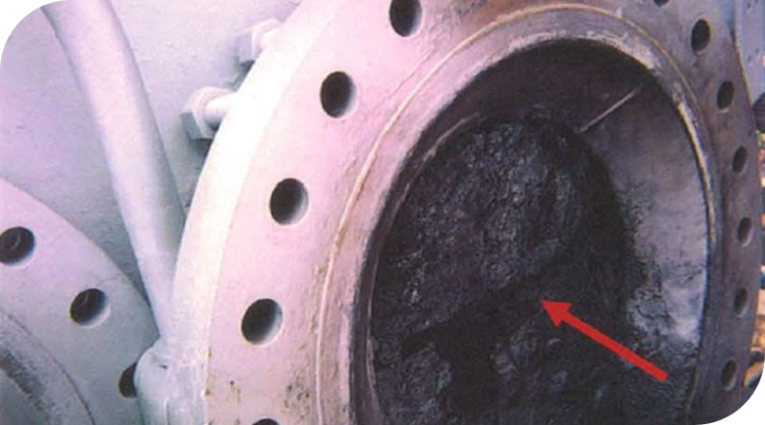
Figure 6 - coke deposition on the transfer line - source: FCCSA’s archives
All the points raised previously must be taken into consideration when deciding on maximizing LCO by reducing severity in the converter, through lowering the reaction temperature and reducing the catalyst/oil ratio.
In terms of maximizing diesel, adjustments to the main fractionator can make more difference than adjustments to the converter. These adjustments are aimed at maximizing the incorporation of naphtha and slurry fractions into the LCO, thus increasing the volume produced.
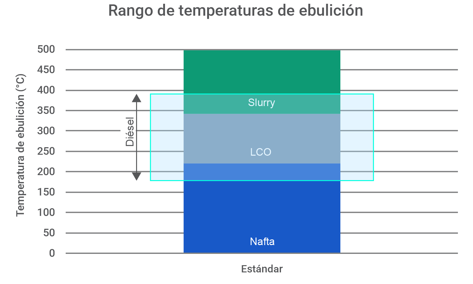
Figure 7 - Comparison between standard cut ranges of FCC products and the distillation range of diesel
LCO was, for a long time, a disregarded product of the FCC unit. Its high content of aromatic and olefinic hydrocarbons, as well as the high levels of nitrogen and sulfur, make its direct incorporation into the refinery's diesel pool difficult or even impossible. Due to the changes in diesel specifications and the increase in the number of hydrotreatment units, which operate with increasing severity and increasingly advanced catalysts, the LCO fraction is now fully incorporated into the diesel pool and becomes important both for volume gain and for property adjustment, such as the cloud point, for example.
As refining schemes have evolved and continue to evolve, FCC units are adapting to the new reality, since the original design of many of the fractionators was not intended for maximizing middle distillates, and sometimes not even for good fractionation. Due to the characteristics of each project, there may be more or less flexibility for adjustments.
It mainly consists of adjusting the fractionator to minimize the endpoint of the light naphtha by reducing the fractionator’s overhead temperature. This adjustment has four main limitations:
In diesel treatment units the fuel must be in liquid phase, thou many of them can tolerate very low fractions of vaporized feed. Therefore, the initial boiling point of LCO is an important parameter to be evaluated when it comes to maximizing naphtha incorporation. Each hydrotreatment unit will have its own limitation.
Reducing the end point of cracked naphtha can interfere with its octane rating. This is because some high-octane aromatic compounds have boiling points starting at 100ºC, and increasing the final boiling point of the naphtha increases the concentration of these compounds, as exemplified in Figure 8. The refinery must, therefore, internally assess the ideal end point for the cracked naphtha.
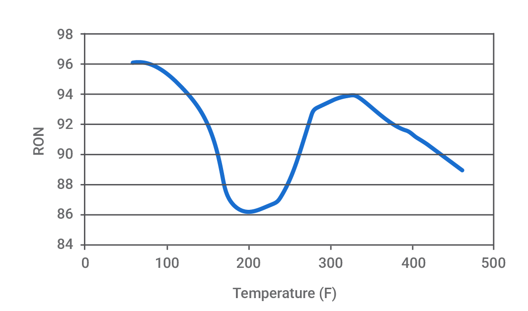
Figure 8 - Variation of the naphtha RON according to the boiling point - Source: PetroSim manual
In addition to the limitations related to product quality, special attention must be given to avoid the formation of chlorine salts at the main fractionator’s overhead system. Reducing the overhead temperature to values below the ammonium chloride’s deposition point can lead to the accumulation of these salts on the internals, which, besides causing severe corrosion, worsens the fractionation due to inefficient contact between liquid and gas and, consequently, leads to the entrainment of heavier compounds, that should have remained in the heavy naphtha and LCO streams, for the cracked naphtha.
The worsening of the fractionation efficiency raises the end point of the light naphtha and increases its sulfur content, which causes the refinery to reduce the column’s overhead temperature even more, thus creating a cumulative effect that is only resolved when an internal cleaning procedure is performed. These deposits can be mitigated through the use of salt dispersants, but it is important to remember that this may lead to the transfer of chlorine salts to the hydrotreatment units, where they can cause corrosion, blockages, and catalyst deactivation. The ideal is to invest in efficient crude desalting and keep the main fractionator’s overhead at a temperature of at least 5ºC above the salt deposition temperature, as well as to avoid the use of catalyst technologies that contain chlorine.
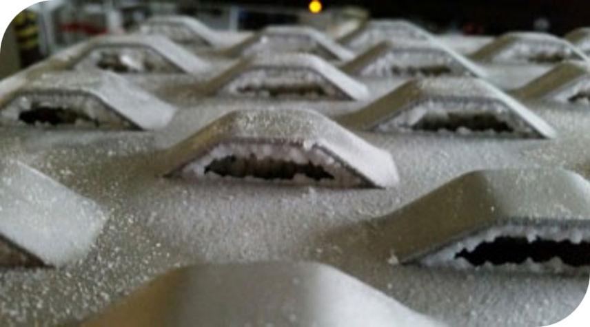
Figure 9 - Salt formation on trays - Source: Sulzer (3)
In addition to the deposition of ammonium salts, the formation of an aqueous phase can occur at the main fractionator’s overhead system if the temperature is below the water’s dewpoint. The presence of this water can cause instabilities in the column and serious fractionation problems if there are no means to remove it, as well as corrosion in internals and damage to heavy naphtha pumps.
The heavy cracked naphtha is the main fractionator’s upper pump around. In some units, there is the possibility of sending this product, which has a distillation range close to that of kerosene (200ºC-300ºC), directly to the hydrotreatment units. This withdrawal can be a good alternative for units where there are flow rate limitations for LCO withdrawal and, since it is easier to treat than LCO due to its lower sulfur content, it can also be sent to units that have limited severity or are having difficulties treating the LCO.
When withdrawing heavy cracked naphtha, attention to the light naphtha’s quality is needed. The reduction of liquid flow below the heavy cracked naphtha’s withdrawal can interfere with the fractionation between naphtha and LCO, leading to an increase in sulfur in the light cracked naphtha and to the presence of heavy hydrocarbons in this stream, even when distillation curves are normal. To identify this poor fractionation, it is important to observe any anomalies in the cracked naphtha hydrotreatment’s deactivation curve and to perform sulfur speciation analysis to identify the presence of high boiling point compounds.
While the standard end point of LCO is 343ºC, diesel’s final boiling point, depending on local specifications, can reach up to 400ºC. This opens up the possibility of incorporating a portion of slurry into the LCO. This increase in the final boiling point is achieved by raising the main fractionator’s bottom temperature.
For this adjustment, there are two main limitations:
LCO must be treated in diesel hydrotreatment units so that it can be significantly incorporated into the blend. When compared to atmospheric distillation diesel, LCO has a higher concentration of aromatic, olefinic, nitrogen, and sulfur compounds, which makes its treatment more complex, especially when the goal is the production of ultra-low sulfur diesel (ULSD).
In LCO fractions with a boiling point above 310ºC, there are sulfur-containing hydrocarbons that are refractory to hydrodesulfurization, such as methyl, dimethyl, and trimethyl-dibenzothiophenes, which require more severe treatment conditions for sulfur removal. This can become a problem in meeting the ultra-low sulfur diesel specifications in units operating under milder reaction conditions. The presence of nitrogen compounds that are also refractory to hydrotreatment, such as alkylated indoles and carbazoles, can affect the quality of the final diesel. Even in medium and high severity units, it is important to know that the higher the presence of these refractory compounds, the shorter the lifespan of the hydrotreatment catalysts. Therefore, properly managing LCO’s quality is an investment in extending the inventory's lifespan.
In addition to making LCO’s hydrotreatment more difficult, increasing the yield of LCO by increasing its final boiling point endpoint can result in coke formation in the main fractionator’s bottoms system, which includes not only the bottom of the column itself but also piping, pumps, and heat exchangers within the slurry circulation’s system. This coke formation can have two main causes: high residence time and low velocity inside the heat exchangers.
When increasing the bottoms’ temperature, the rate of thermal cracking reactions, that naturally occur in hydrocarbons subjected to high temperatures, increases, which is exacerbated by the fact that the slurry contains a high concentration of polyaromatics, with a greater tendency for condensation and polymerization reactions. At the same time, with the reduction of its yield, the slurry spends more time circulating within the bottoms system, subjected to this high temperature. It is precisely the slurry’s residence time that defines the maximum bottom temperature for this column:
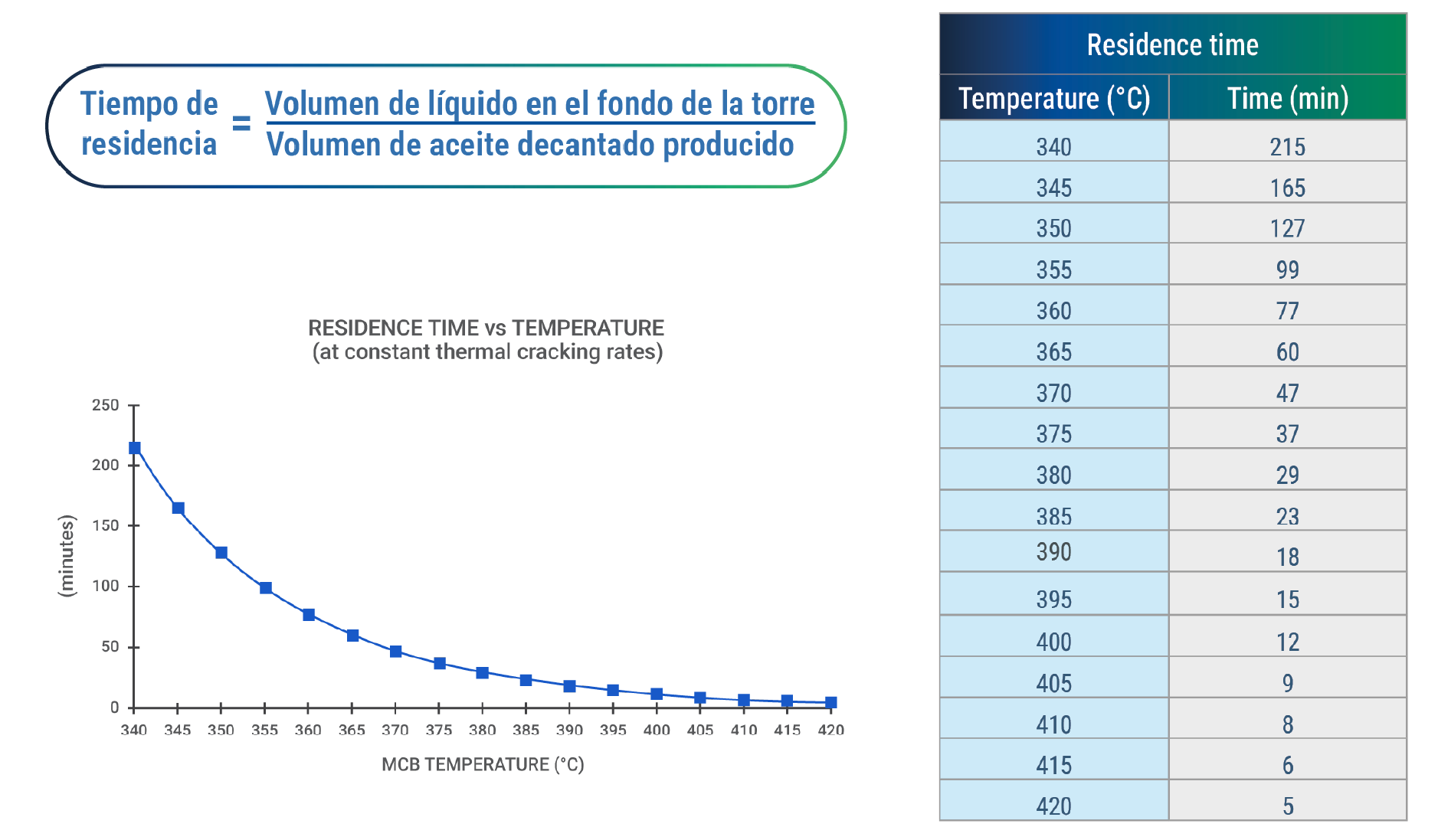
Figure 10 - maximum residence time as a function of temperature - Source: E. Brevoord, J.R.Wilcox (4)
The formed coke can accumulate in the fractionator itself, pump filters, heat exchanger tubes, and pipes, especially at regions with smaller diameters and lower velocities. Small pieces of coke can, for example, completely block heat exchangers’ tubes. (Figure 11)
There is also a need to monitor the slurry’s velocity through the heat exchangers tubes, which creates a minimum limit for this product’s pump around. Due to the presence of catalyst, it is important to maintain a minimum velocity inside the tubes (1.5 m/s) to prevent the catalyst from depositing.
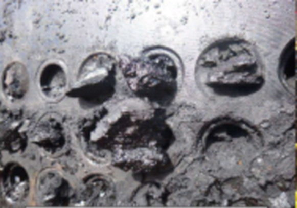
Figure 11 - Heat exchanger blockage by coke - Source: FCCSA’s archives
The UFCC’s catalytic system optimization for maximizing diesel is a valuable resource, as it allows for an additional increase in LCO yield while the unit operates within its safe limits. These special formulations maintain the conversion of bottoms to LCO while limiting the cracking of LCO to naphtha, allowing an increase in LCO yield under the same operating conditions.
In these formulations, zeolite is no longer the main protagonist, and the focus is on using matrices with high activity and high accessibility to maximize bottoms conversion. The zeolite/matrix ratio in these catalysts is balanced to maintain the production of high-quality naphtha and the possibility of maximizing olefins if that is the unit's objective.
Some refineries that use catalysts with a high zeolite-to-matrix ratio end up reducing the catalyst’s specific makeup in an attempt to increase the LCO yield, reasoning that increasing the concentration of contaminants in the inventory will naturally reduce zeolite activity, which in turn decreases the conversion of LCO to naphtha. This strategy is risky and can cause a series of inconveniences to the refiner:
The desired characteristics for a catalyst dedicated to maximizing diesel are:
FCCSA offers a family of catalysts that combines all these characteristics: UPGRADERTM MD. These are catalysts that promote not only an increase in LCO yield but also an increase in the LCO/slurry ratio.
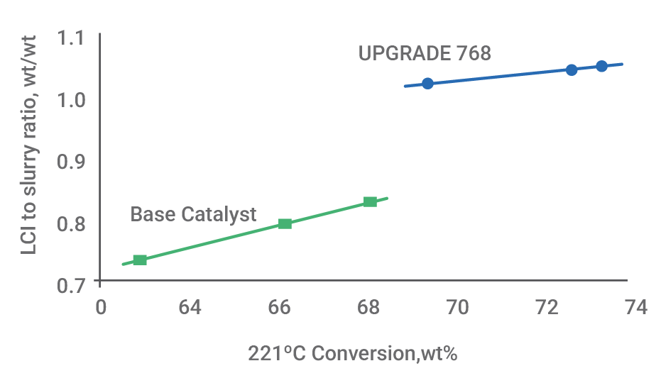
Figure 12 - Effect of UPGRADERTM MD on the LCO/bottoms ratio, (m/m %). (5)
The experience of replacing high zeolite/matrix ratio catalysts with UPGRADER™ MD family catalysts demonstrates that, at the same reaction temperature, it is possible to increase the LCO yield without increasing slurry production, which enhances the unit's profitability without the need for excessive severity reduction, helping to preserve the unit’s integrity.
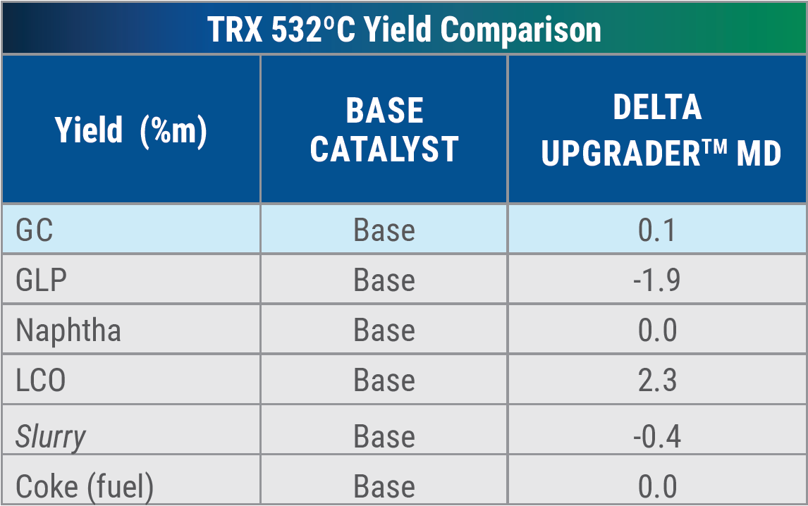
Table 2 - Variation of mass yields with the change of base catalyst for the UPGRADERTM MD - Source: Ketjen database
FCCSA’s technical services team can help you optimize your unit. We are specialists with a broad perspective, with experience in refining and advanced knowledge in process optimization. We are at your service.
Related Publications


What did you make of the publication?