


Form sent successfully!


Be acquainted with our purpose, values, history and all that makes the FCC S.A. essence

A portfolio of products and solutions plenty of innovation, technology and sustainability.

To deliver products with leading edge technology and global quality is just our starting point. That is why we have a series of exclusive services for our customers and that make all the difference on a daily basis.

See in practical terms how innovation is present in the FCC S.A. DNA

Sustainability is present in every solution, delivery and process of our company: learn more.

We are made of synergy! Learn how you can become a FCC S.A. supplier

Learn how it is to work with FCC.S.A. Learn our culture, programs and check for opportunities.

Integrity and transparency are part of what we are. Check our annual reports and see the result of our work.

Find a variety of contents that permeate our businesses and see how you can be a part of what we create around here.

Together, we create more! Be a FCC S.A. partner and generate value for a world in transformation: learn how.

It starts discreetly. A small increase in pressure in the main fractionator, a small increase in sulfur and the end point of the naphtha, nothing that an adjustment cannot fix. A little increase in the reflux flow rate, a little reduction in the compressor’s suction pressure. Simple, quick, corrected so easily that no one notices the changes.
Time passes, and with each adjustment, the team realizes that something is not right. The compressor is running at maximum for the same feedstock, you look at the history of the fuel gas composition, the hydrogen concentration is a bit higher than it was weeks ago, that could be it. In the catalyst, the metals’ concentration is the same, so maybe it is the antimony pentoxide that is not working well, maybe it is an adjustment in the converter. The team adjusts and works around the problem.
Meanwhile, the fractionator is pressurized, the overhead temperature is much lower than normal to control the final boiling point, the reflux valve is at maximum opening, and yet the naphtha does not improve, the sulfur is high, and the treatment unit is stressed to deal with poor quality naphtha.
To make matters worse, a leak appears in one of the overhead condensers. Isolate the exchanger, wash it to be able to inspect. The equipment is completely clean, but the corrosion marks are there, the thin walls, and another beam to be replaced during the next turnaround. The perforated tubes are sealed, and the heat exchanger is back to operation.
The daily routine continues, the engineer already suspects obstructions in the exchangers, dirty trays in the column, it could be the infamous salt. We cannot attempt to wash the column now; the maneuver carries risks, and besides, the refinery needs the unit operating at maximum load.
An unplanned shutdown and everything disappears, after all, the vast majority of ammonia salts are soluble in water. The fractionator is working well, low pressure, good fractionation. The compressor unrestricted. Whatever caused this problem is over, we have other priorities, the operation continues as if nothing had happened.
From adjustment to adjustment, the cycle repeats. Fractionation problems, compressor overload, severe corrosion. This is the routine of refineries that deal with a very common problem in FCC units, the formation of salt deposits in the fractionator’s overhead system.
To contain this deposition, some refineries choose to perform periodic washing procedures in the main fractionator, while others use chemical salt dispersants. These actions help to mitigate and reduce the severity of the consequences associated with salt formation, but they do not eliminate the root cause of the problem since, in most cases, it is not located in the FCC unit.
In FCC units, the most commonly formed salt is ammonium chloride (NH4Cl), which crystallizes directly from the gas phase when the partial pressures of NH3 and HCl become high enough. Under normal conditions, this salt crystallizes only in the fractionator’s overhead condensers, which usually undergo routine washing procedures, but depending on the concentrations of NH3 and HCl this crystallization can occur on the overhead trays, impairing the contact between gas and liquid and light naphtha’s fractionation of, which leads to an increase in sulfur and the final boiling point.
Ammonia forms naturally in the riser. Part of the nitrogen present in the feedstock is converted into ammonia, a fact that is often overlooked by the refinery; after all, does anyone monitor the ammonia’s concentration in the fuel gas? But it is there, reaching hundreds of kilograms per day, flowing into the sour waters. We only remember it when we sample these sour waters, if we even sample them at all. Concentrations that can exceed 10,000 ppm are more concerning to the engineer in charge of the stripping columns that will treat this water than to the FCC engineer. Ammonia will always be there in abundance, but that is not the focus of this article.
What really determines whether an FCC unit will suffer from salt formation is the presence of higher or lower concentrations of chlorine, because this determines the sublimation temperature and pressure of NH4Cl in the main fractionator’s overhead system, since the chlorine that reaches the riser forms HCl. The higher the concentration of chlorine, the higher the temperature at which this salt deposition begins, and this chlorine has three main sources:
In addition to the formation of salts in the main fractionator’s overhead system, chlorine is capable of reactivating nickel that was already oxidized in the catalyst, restoring its dehydrogenating power and increasing the concentration of H2 in the fuel gas.
The main source of chlorine for the FCC unit is the unit’s feedstock, and the cause of excess chlorine is usually inefficient desalting. Increased load of the distillation unit, inadequate temperature of the crude, changes in the refinery’s crude diet, there are several reasons why the desalting system may not adequately remove chlorine. The challenge becomes greater with the new crudes available in Latin America, rich in calcium and magnesium salts that are poorly soluble in water, and that contain organic chlorides, which are not removed in the desalting process.
The unit that suffers the most from the consequences of poor desalting is the distillation unit, where calcium and magnesium salts can hydrolyze, releasing chlorine, which forms HCl and corrodes the overhead systems of the columns, and where organic chloride can also be released. Therefore, these units usually have strict control over corrosion mechanisms, with injections of chemical products to control the action of chlorine. In these units, the chlorine that comes from the desalting systems is usually measured by the salt analysis as NaCl, but what happens afterward?
Due to the release of chlorine in the distillation unit’s columns, some streams concentrate more chlorides, particularly the light vacuum gas oil, which is usually a feedstock for the FCC. Chlorine will also be present in heavy diesel streams, atmospheric residue, heavy vacuum gas oil, and vacuum residue.
Not all FCC units have strict feedstock quality control. Ideally, routine feedstock tests should be performed frequently, several times a week, and these tests should include salt or chloride analyses. Failing to frequently measure chlorine levels in the feedstock can prevent the refinery from taking preventive actions in the face of a concentration increase, causing this increase to be noticed only when symptoms such as system blockage appear.
The presence of chlorine in the steam injected into the riser and columns in the FCC unit is less common, but it can occur due to poor desalination of demineralized water or contamination of that water or steam. This contaminant’s presence identification is made through analyzing the condensate. The poor quality of the steam will also affect steam generators and turbines.
Lastly, some FCC catalyst technologies contain chlorine in their formulation, and this chlorine is released in the riser, but it does not appear in the catalyst composition tests. Even with chloride control in the feedstock, the unit may suffer from salt deposits in the overhead system without being able to identify the source of this contamination. If you use FCC S.A. catalysts, do not worry, our catalyst is chlorine-free. If you are not our customer and suspect that the catalyst may be a source of chlorides, the technical services team at FCC S.A. is here for you.
To discover the origin of the chlorides and to verify if there is an accumulation of salt in the FCC, it is important to map the path of this contaminant through the chloride balance.
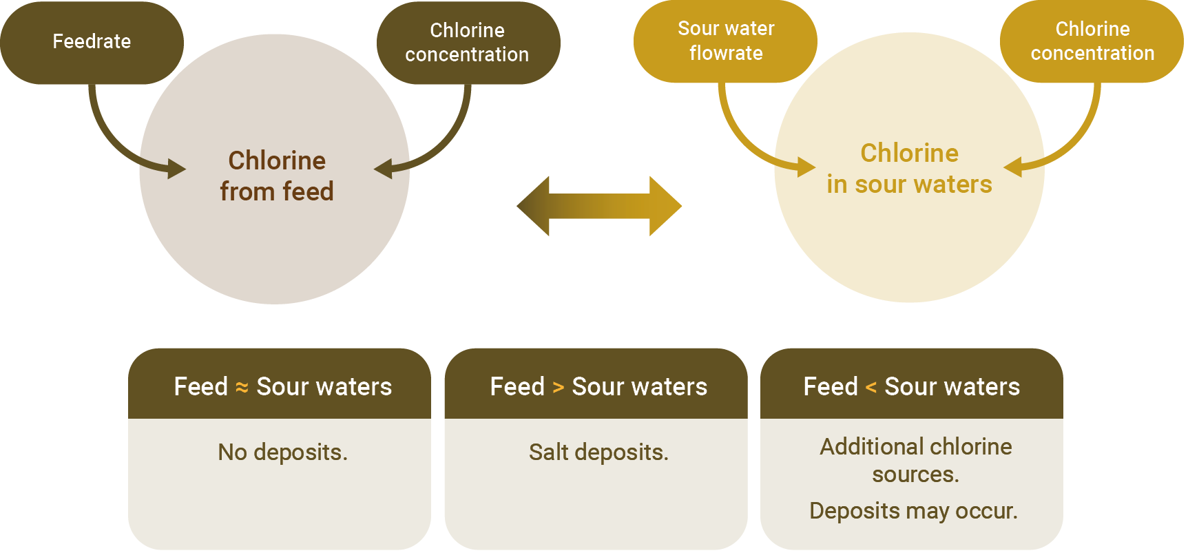
Figure1 - Chlorine GPS. Source: FCC S.A.
Measuring the chlorine in the feedstock is the first step. It is important to monitor this contaminant and limit its concentration in the feedstock to prevent the occurrence of salt deposits in the unit. Some refineries directly measure the chloride in the feedstock, some refineries use the same salt measurement method as NaCl used for crude oil, the methods vary, the important thing is to measure how much chlorine comes in with the feedstock.
The second step is to monitor the concentration of chlorine in the unit’s sour waters their flow rates. In addition to the steam injected into the converter and main fractionator, FCC units commonly have scrubbing systems for the main fractionator’s overhead condensers and for the gases in the wet gas compressor system, the chlorides will exit the unit solubilized in these sour water streams. The refinery has two options: measure the concentration of chlorine and the flow rate of each of the sour water streams or perform the measurement of the flow rate and concentration of the combined sour water stream that leaves the unit.
With the mass of chlorine that enters the unit and the mass that exits through the sour waters, it is possible to evaluate the chlorine balance:
The monitoring of significant deposit occurrences also involves tracking the pressure drop in main fractionator’s overhead system, which allows for checking whether the washing of the overhead condensers is sufficient and if deposits are occurring in the fractionator.
The easiest way to do this is to create tracking charts for the last few months (we suggest about 6), one with the pressure drop between the heavy naphtha reflux region and the main fractionator’s top outlet(salts tend to deposit on the top trays) and another with the pressure difference between the main fractionator’s top outlet and the wet gas compressor’s first stage suction drum. This way, it becomes easy to identify changes that indicate the beginning of salt deposition, allowing for mitigation actions.
To prevent the deposition of salts in the FCC main fractionator, it is recommended to operate with a overhead temperature 5 ºC higher than the deposition temperature of ammonium chloride.
To calculate this temperature, in addition to the chlorine flow that reaches the unit, it is necessary to calculate its molar concentration at the fractionator’s overhead. For this, it is possible to use the molar flow rate estimates made via a simulator or calculate the molar flow rates using chromatography and correlations to calculate the molecular weight of each stream that derives from the main fractionator’s overhead stream:
As an example of correlations for calculating the molecular weight of liquid streams, we have the Riazi-Daubert method:

In this equation, Tb is the average boiling point in K and SG is the relative density at 15.6 ºC.
Do not forget to exclude external streams that reach the unit after the main fractionator. From the molar flow rate of the top stream of the fractionator, it is possible to calculate the molar concentration of chlorine.
The deposition temperature of NH4Cl at the top of the fractionator will be calculated using the following equilibrium equation:

In this equation PvNH4Cl is the partial pressure of NH4Cl in the stream, in kPa, and T is the temperature of salt deposition, in K.
To calculate the PvNH4Cl, it is assumed that it is equal to the partial pressure of chlorine:

Where yHCl is the molar fraction of HCl in the overhead stream of the main fractionator and Pt is the total pressure of the fractionator, in kPa.
The margin of 5 ºC above the salt formation temperature allows for the absorption of small variations in chlorine concentration that occur daily at the refinery, but not large variations. Furthermore, we know that the main fractionator cannot operate at very high temperatures, as there is a need to adjust this variable to control the light cracked naphtha’s final boiling point. Therefore, properly controlling the quality of the feedstock is necessary, with the establishment of a maximum concentration limit of chlorine (or salt) that is in accordance with the main fractionator’s operational temperature range that allows for the specification of the cracked naphtha.
It is important for the entire refinery to understand that this control is essential, as the deposits occur in a short time and the reversal of these deposits requires operational maneuvers that lead to the generation of large volumes of off-spec products and/or shock dosages of chemicals that also affect the quality of FCC products.
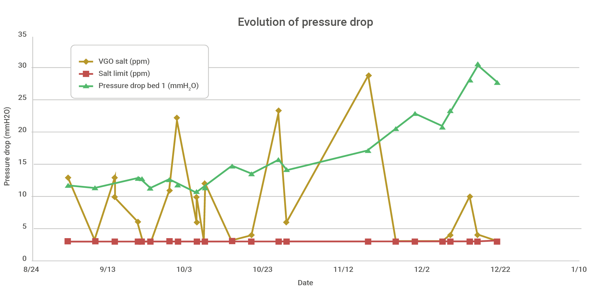
Graph 1 – Real-world example of pressure drop evolution at the top of the fractionator during operation above the chlorine limit in the feed.
Some refineries choose to continuously use salt dispersant chemicals in the overhead system as a form of prevention. It is an alternative that may work well for some refineries and should indeed be studied, but it is important to be aware that:
Another little-remembered preventive action is the control of the temperature of the upper circulating reflux. Special care must be taken by refineries that use heavy cracked naphtha as sponge oil in the secondary absorber, since the operating temperature of the absorbers is low, and the return of this stream must be pre-mixed with the circulating reflux before entering the fractionator. The recommended minimum temperature is 105 ºC.
In the main fractionator’s overhead condensers system , where ammonium salts will inevitably form, preventive actions will be aimed at avoiding corrosion in the system.
The main preventive action, and in most cases the only one needed, is the periodic washing of these condensers with water. Some refineries have automated systems, with timed water injections for each of the condensers, while others alternately fill these condensers with water a few times a week. There is also the possibility of using salt dispersant additives in this area.
For timed injection systems, it is important to ensure that at least 30% of the injected water remains in liquid form under the conditions inside the equipment. It is also important for any system that this water is relatively clean, without significant concentrations of calcium and magnesium to avoid the formation of poorly soluble salts. Monitoring the pressure drop between the column’s overhead and the compressor suction helps to identify whether the washing regime is sufficient or if, in the case of a gradual increase in this pressure drop, intensification of the washings is necessary.
From the moment the formation of salts at the top of the fractionator is identified, the main mitigation alternatives are:
Theoretically, raising the top temperature to a level of several degrees above the salt formation temperature could also be an alternative, but it is not usually very effective.
Each refinery has its own procedure for washing the top trays of the main fractionator. Some have special configurations that anticipate these maneuvers, while others do not, but there are some common precautions that should be taken:
When the shocl injection of salt dispersantsis the refinery’s option, it is important to divert light cracked naphtha, heavy cracked naphtha, and LCO from hydrotreatments due to the possible presence of salt in these streams.
The correction of chronic salt formation issues at the main fractionator’s overhead system is to address the source of excess chlorine, and this can impact the refinery as a whole.
When the source of excess chlorine is the FCC catalyst, the solution is simple: switch to a chlorine-free catalyst. None of the FCC S.A.’s catalysts contain chlorine in their formulation, and we can offer the best catalytic solutions for our clients.
In cases of steam contamination with chlorides, it is necessary to investigate whether the source is due to leaks in heat exchangers or if it is due to inefficient treatment. While a leak only requires maintenance, correcting inadequate treatment requires investments, which can be as simple as replacing membranes or totally upgrading the water demineralization plant with more efficient equipment.
Investing in better water demineralization benefits the refinery as a whole, helping to preserve steam generators and turbines, as well as reducing contamination of the FCC catalyst, which suffers from the presence of salts in the steam injected into the converter. With the reduction of maintenance in steam generators, lower catalyst consumption, and preservation of the FCC unit’s capacity by reducing salt formation in the overhead system, this investment in water treatment pays off quickly.
Solvingproblems in the desalters is a bit more complex because it is necessary to investigate the causes of the high concentration of chlorine in the desalted crude, which usually is a combination of more than one.
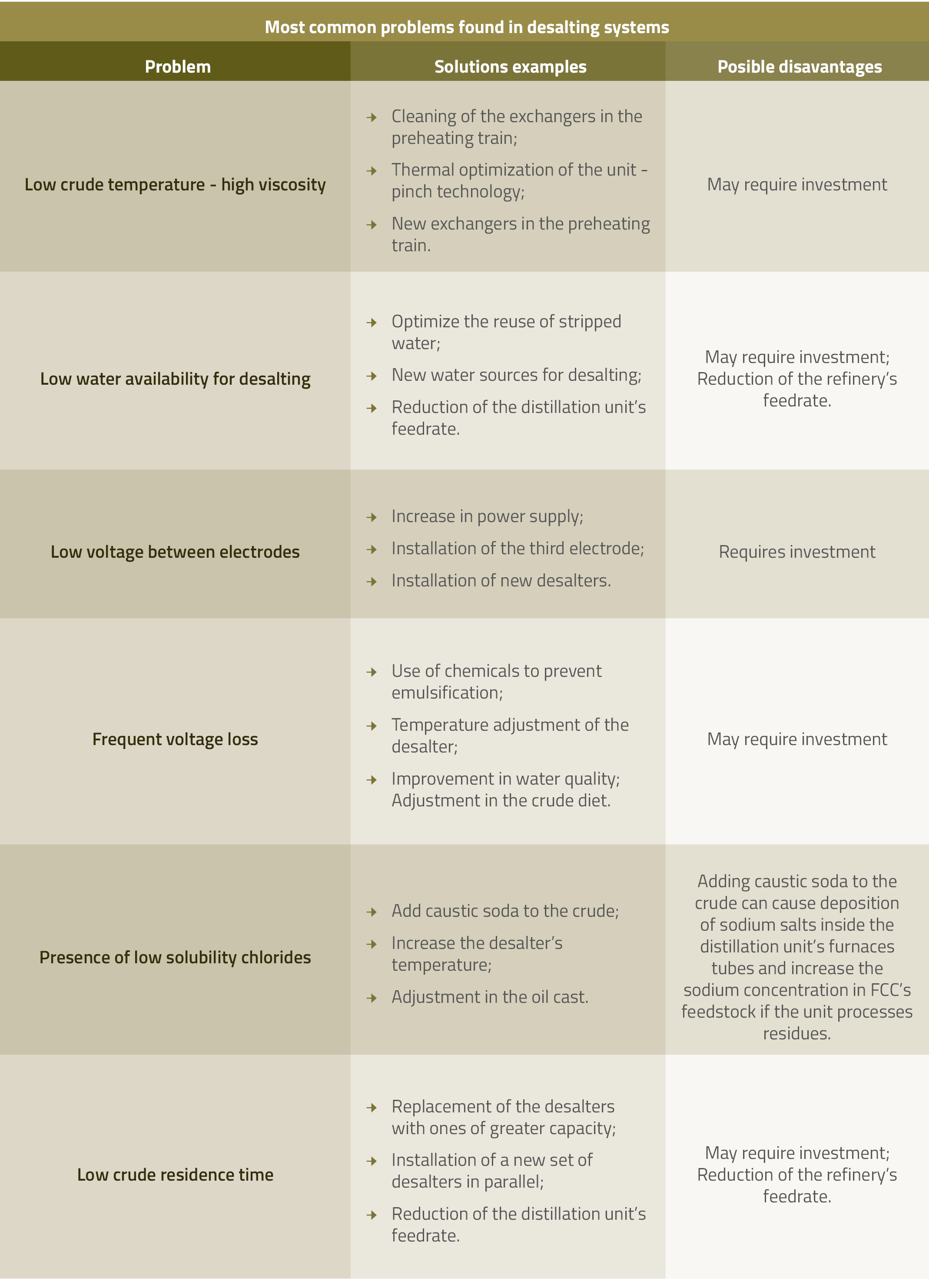
Once the cause is identified, the solution can be simple, such as cleaning some heat exchangers, or it may require the implementation of new projects along with a reduction in the refinery’s feed until the project is implemented. Investing in good desalting will not only fix problems in the FCC unit, but it will also greatly improve the performance of the refinery as a whole:
The table below presents some of the most common problems in desalting systems and their possible solutions:
The presence of excessive chlorine concentrations in the FCC unit’s feedstock is a problem that is often underestimated until its consequences impact the unit’s feed rate, its integrity, and the quality of its products.
Preventing, mitigating, and correcting the formation of salts in the top system of the main FCC fractionator is a task that does not fall solely on the team working in that unit, but rather a commitment from the entire refinery to the integrity and performance of its main units. Distillation, FCC, coking, hydrotreatments, all are negatively affected by the presence of chlorine, which fully justifies investments aimed at improving systems that reduce the impact of this contaminant.
The technical services team at FCC S.A. can help you with issues that go beyond the FCC unit converter. We are specialists with a broad perspective, with experience in refining and with the support of the technical teams from Ketjen and Petrobras. We are at your disposal.
Related publications
What did you make of the publication?